

Professional Power Resistor Essentials for Reliable Circuit Performance
2026-08-16
Every circuit tells a story, and power resistors are the quiet characters that keep the plot from overheating. But not all resistors are cast for the same role. At Milliohm, we believe reliable circuit performance starts with components that don’t just meet specs—they anticipate stress, drift, and the unexpected. This guide cuts through catalog noise to explore what makes a professional power resistor truly essential: thermal design, tolerance under load, and materials that hold their character when temperatures climb. Whether you’re designing for industrial drives or precision instrumentation, the difference between a good board and a great one often lives in the details most overlook. Let’s pull back the curtain on those details.
Why Resistor Choice Quietly Determines Circuit Lifespan
At first glance a resistor seems too simple to influence how long a circuit survives, but the materials inside set a slow degradation path. Carbon film parts drift noticeably after years of temperature swings, while quality metal film or thin film resistors hold their value far tighter. That drift alone can push an analog bias point out of range, forcing a transistor to dissipate more heat or a timing loop to wander until the product behaves erratically.
Power rating is where lifespan gets decided long before the resistor actually fails. Running a part near its rated wattage keeps the body hot enough to accelerate element aging and weaken nearby solder joints. In humid or high-voltage environments, a warm resistor also becomes a site for electrochemical migration across the board surface. Even brief current surges that stay under the continuous rating can cause tiny internal hot spots, especially in thick film parts, and those micro-damage events accumulate into permanent value shifts.
Tolerance stacking and long-term drift matter most in feedback and reference circuits. A regulator that depends on two resistors for its output voltage can wander just enough to overstress downstream capacitors or alter charge currents for batteries. Choosing a resistor with a lower temperature coefficient, stable construction, and generous derating often adds only a few cents to the bill of materials. That small margin is frequently what separates a product that works for a decade from one that develops mysterious intermittent faults after the warranty expires.
Thermal Behavior: What Datasheets Don't Spell Out
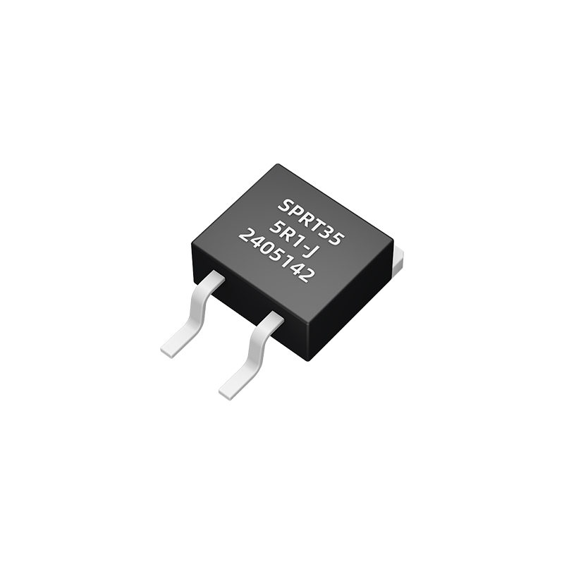
Most engineers treat thermal resistance numbers in datasheets like fixed constants—plug them into a junction-temperature equation and move on. Reality is messier. The θJA value printed on page three assumes a specific board layout, copper pour area, and ambient airflow that rarely matches your actual PCB. Solder a part onto a dense multilayer board with internal ground planes, and the true θJA might drop by 30%; mount the same part on a thin two-layer flex board with no thermal vias, and it could double. Those hidden variables never show up in the parametric table.
Even the θJC value—often quoted as the "best-case" thermal path—carries an unspoken caveat: it is measured with the case pressed against an isothermal cold plate, not a real heatsink with mounting pressure, thermal grease thickness, and surface flatness tolerance. In practice, the interface resistance between package and heatsink can dominate the total thermal stack, yet datasheets leave you to guess how much margin to subtract. What also stays unmentioned is the package's internal thermal spreading: a tiny die in a large QFN may have a low θJC on paper, but local hot spots near high-power output transistors can push the junction temperature 15–20°C above the spatially averaged value.
Then there is the dynamic behavior. Datasheets list steady-state thermal impedance as a single number, but power dissipation in real circuits fluctuates with load and switching frequency. The thermal time constant of the package—often tens of seconds for a power device—means a short overload pulse may not overheat the silicon, while a sustained moderate load above the assumed duty cycle can cause thermal runaway. Few datasheets bother to show the transient thermal impedance curve in a readable form, let alone warn that adjacent heat-generating components on your board can raise the local ambient well beyond 25°C, quietly invalidating every thermal calculation you based on the printed spec.
Matching Wattage Ratings to Real Operating Conditions
Power ratings stamped on a chassis rarely survive contact with a live circuit. Heat soak, aging electrolytics, and brownout conditions all claw back the headroom that a bench test assumes. A converter rated for 500 watts at 25°C can limp badly once the intake air climbs past 40°C, especially if the enclosure traps heat near the switching devices.
The useful figure is not the single printed number but the derating curve plotted against temperature and altitude. Loads that are mostly capacitive or heavily inductive can also draw current in ways that punish a supply rated only for resistive testing. Checking the fine print for continuous versus peak output, and then measuring actual draw over a full thermal cycle, prevents most field failures.
Construction Details That Separate Robust Parts from Fragile Ones
You can feel the difference the moment you pick up a well-built part. It isn't just weight or thickness, though those play a role. It's the way corners are radiused instead of left sharp, the way a boss blends into a wall, and the way a rib doesn't end abruptly but tapers into something that looks intentional. These small choices add up, and they are what separate a part that survives a drop from one that cracks on the first impact.
Think about how material flows into a mold or how stress travels through a bracket. A fragile design ignores those paths; it puts a sharp inside corner where the material is already thin, or it lets a wall stay perfectly flat without any cross-bracing. A robust one adds a gentle fillet, a subtle draft, or a well-placed gusset. These aren't decorative extras. They are structural decisions made before the first prototype is ever printed or machined.
The real test comes after assembly. A fragile part needs careful handling, a specific orientation, maybe even a warning label. A robust part gets thrown into a bin, bolted down without a torque wrench, and still holds up years later. That kind of durability doesn't happen by accident. It comes from understanding where loads concentrate, where fatigue starts, and where a tiny design change can stop a crack before it ever begins.
Placement and Cooling Tactics That Prevent Early Drift
Getting the initial setup right often matters more than constant mid-print corrections. Rather than defaulting to the center of the build plate, shift the model toward the intake side if your printer has a directional cooling fan. This simple move means the air stream hits the part more consistently during the critical first few layers, reducing the chance of one edge lifting while another stays anchored.
Cooling itself needs a gentler hand early on. Blasting a fresh print with full fan speed can chill the filament unevenly, creating internal stress that slowly pulls corners away from the bed. A smarter approach is to keep the fan off or very low for the first two or three layers, then ramp it up gradually. For materials like PETG or ABS, that ramp should be even slower, letting the layers bond fully before they face active airflow.
Placement also includes the orientation of the part on the plate. Tall, narrow sections catch more airflow and cool faster than wide bases, so rotating the model so those features sit away from the fan’s direct path can prevent warping on one side. If your printer allows it, a quick test with a small sacrificial print at different positions will reveal exactly where the cooling is most even, saving time and filament on larger jobs.
Spotting Failure Modes Before They Take Down the Board
Failure rarely announces itself with a formal memo. It creeps in through small, unglamorous cracks: a supplier who misses two deadlines in a row, a board member who stops asking hard questions, a product metric that flatlines while everyone celebrates the launch party. The trick is to treat these early tremors not as annoyances but as data. Most boards only look backward at failure, dissecting what went wrong after the bleeding starts. A better practice is to build a forward radar: map the handful of assumptions your strategy depends on, then track the leading indicators that would disprove them. If customer churn is a core risk, don't wait for the quarterly report—watch support ticket sentiment weekly. If a key hire is the linchpin, monitor their engagement signals before the resignation letter lands.
Boards often fall into the trap of celebrating consensus. When everyone around the table nods in agreement, the room feels safe, but that's precisely when blind spots harden. One practical fix is to assign a rotating “devil's advocate” role whose only job is to pressure-test the rosy narrative. Another is to insist on pre-mortems for major decisions: imagine the initiative has already failed, then work backward to list the most plausible causes. This shifts the conversation from “why we're right” to “how we could be wrong,” which surfaces failure modes long before they become visible to the outside world.
What ultimately saves a board is not a perfect crystal ball but a culture that rewards early warnings. If a junior analyst feels uncomfortable raising a red flag because the CEO is in the room, you've already lost the early detection game. Normalize the phrase “I might be seeing ghosts, but…” and treat every near-miss as a free lesson. The difference between a board that navigates turbulence and one that gets blindsided is rarely intelligence—it's the willingness to look at ugly truths while they're still small enough to fix.
FAQ
Professional power resistors are built to dissipate substantial heat while maintaining stable resistance, using materials like wirewound, thick film, or metal foil with high thermal conductivity. They specify continuous and pulse power ratings, low temperature coefficients, and often include mounting features for heatsinks, whereas standard resistors typically assume minimal self-heating and lower stress.
Calculate expected power as I²R or V²/R, then apply a derating factor of at least 50% under normal ambient conditions. If the resistor operates above its rated temperature or in an enclosure with poor airflow, derate further according to the manufacturer's power-temperature curve. This ensures the hotspot stays within safe limits.
Power resistors convert excess electrical energy directly into heat; without a proper thermal path, the resistor body can reach temperatures that degrade the element, solder joints, and nearby components. Effective heatsinking, forced air, or PCB copper pours reduce thermal resistance and improve long-term reliability.
TCR indicates how much the resistance shifts with temperature. In high-precision or high-temperature circuits, a low TCR (e.g., ±50 ppm/°C or better) keeps resistance stable as the part heats up, preventing drift in current sensing, voltage dividers, or load banks. Professional designs often specify TCR alongside power rating.
Pulse loads deliver high energy for short durations, which can cause localized heating and mechanical stress even when average power appears low. A professional power resistor should specify pulse or surge ratings, such as peak power for a given pulse width and repetition rate, to ensure the element doesn't crack, fuse, or change value permanently.
Wirewound types handle high energy and pulse loads well, offer low TCR and high stability, but can have inductance. Thick film resistors are compact and cost-effective for moderate power with non-inductive options. Choose wirewound when you need high precision under sustained high heat, or when pulse energy is a primary concern and inductance is acceptable.
Use thermal interface material between the resistor and heatsink, apply the specified torque for screws or clips, avoid mechanical stress on leads, and follow recommended pad layouts for SMD types. For chassis-mount resistors, ensure flat, clean contact surfaces and consider silicone-based heat compound to fill microscopic air gaps.
Perform accelerated life testing under worst-case conditions—maximum rated power, elevated ambient temperature, and repeated thermal cycling. Monitor resistance drift over time; a professional part should stay within its specified tolerance after thousands of cycles. Also review manufacturer reliability data such as load life and humidity testing results.
Conclusion
Designers often treat resistor selection as an afterthought, focusing on resistance value and tolerance while overlooking the thermal reality that quietly decides circuit lifespan. A power resistor's datasheet rating assumes ideal heat sinking, but real boards rarely provide that. Copper area, adjacent components, ambient temperature, and even enclosure airflow all pull the actual safe operating point downward. A wirewound part stamped 5 W can easily be pushed into thermal runaway if surrounded by hot regulators or starved of convection. The practical rule is not to match the nominal wattage to your calculated dissipation, but to apply a meaningful derating based on the worst-case local environment. Peak pulse energy matters just as much as average power; a resistor that survives steady-state may crack under repetitive inrush transients because its element expands and contracts at a different rate than the core.
Construction details separate parts that last a decade from those that drift after a few hundred thermal cycles. Thick-film, thin-film, wirewound, and metal-foil elements each tolerate pulse loading, moisture, and mechanical stress differently. A robust choice pairs the right element with a compatible end-cap or welded termination, not a cheap crimp that becomes a failure point. On the board, give the resistor enough copper pour to spread heat, keep it away from electrolytic capacitors and precision references, and orient it so natural convection works for you instead of against you. Watch for early signs—discoloration, microcracks in the coating, dull solder joints—because those often precede hard failures by weeks or months. A careful look at steady-state dissipation, transient energy, and thermal cycling beats chasing a higher wattage number every time.
Contact Us
Contact Person: Yuying Gao
Email: [email protected]
Tel/WhatsApp: +86 18926013721
Website: https://en.milliohm.net/